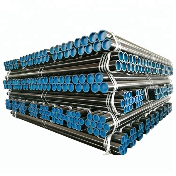
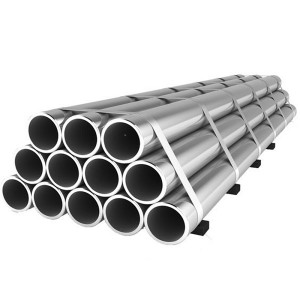
Factory Supply China Ms Round Low Carbon Seamless Steel Pipe Black Iron Seamless Steel Pipe Used for Petroleum Pipeline
Overview
We aim to find out quality disfigurement from the production and supply the best service to domestic and overseas customers wholeheartedly for Seamless Steel Pipe Used for Petroleum Pipeline, If you are fascinated in almost any of our solutions or would want to discuss a custom-made order, remember to really feel absolutely free to contact us. We present the great variety of products and solutions in this area. Besides, customized orders are also available. What's more, you will enjoy our excellent services. In one word, your satisfaction is guaranteed. Welcome to visit our company! For more information, be sure to come to our website.If any further inquiries, please feel free to contact us.
Introduction to API 5L pipeline steel pipe/The difference between API 5L PSL1 and PSL2 standards
API 5L generally refers to the implementation standard of line steel pipes, which are used to transport the oil, steam, water, etc. extracted from the ground to the petroleum and natural gas industrial enterprises. Line pipes include seamless steel pipes and welded steel pipes. Currently, the commonly used welded steel pipe types in oil pipelines in China include spiral submerged arc welded pipe (SSAW), longitudinal submerged arc welded pipe (LSAW), and electric resistance welded pipe (ERW). Seam steel pipes are generally selected when the pipe diameter is less than 152mm.
There are many grades of raw materials for API 5L steel pipes: GR.B, X42, X46, X52, X56, X60, X70, X80, etc. Now large steel mills like Baosteel have developed steel grades for X100, X120 pipeline steel. Different steel grades of steel pipes have higher requirements for raw materials and production, and the carbon equivalent between different steel grades is strictly controlled.
When it comes to API 5L, everyone knows that there are two standards, PSL1 and PSL2. Although there is only one word difference, the content of these two standards is very different. This is similar to the GB/T9711.1.2.3 standard. They all talk about the same thing, but the requirements are very different. Now I will talk about the difference between PSL1 and PSL2 in detail:
1. PSL is the abbreviation for product specification level. The product specification level of line pipe is divided into PSL1 and PSL2, it can also be said that the quality level is divided into PSL1 and PSL2. PSL2 is higher than PSL1. These two specification levels are not only different in inspection requirements, but also in chemical composition and mechanical properties. Therefore, when ordering according to API 5L, the terms in the contract shall not only indicate the usual indicators such as specifications and steel grades. , Must also indicate the product specification level, that is, PSL1 or PSL2. PSL2 is stricter than PSL1 in indicators such as chemical composition, tensile properties, impact energy, and non-destructive testing.
2. PSL1 does not require impact performance. For all steel grades of PSL2 except x80, the average value of Akv at full scale at 0°C: longitudinal ≥ 41J, transverse ≥ 27J. X80 steel grade, full-scale 0℃ Akv average value: longitudinal ≥ 101J, transverse ≥ 68J.
3. Pipeline pipes should be hydrostatically tested one by one, and the standard does not provide for non-destructive substitution of water pressure. This is also a big difference between the API standard and the Chinese standard. PSL1 does not require non-destructive inspection, PSL2 should be non-destructive inspection one by one.
Application
The pipeline is used to transport the oil, steam and water drawn from the ground to the oil and gas industry enterprises through the pipeline
Main Grade
Grade for API 5L line pipe steel: Gr.B X42 X52 X60 X65 X70
Chemical Component
| Steel Grade (Steel Name) | Mass Fraction, Based on Heat and Product Analyses a,g% | |||||||
| C | Mn | P | S | V | Nb | Ti | ||
| max b | max b | min | max | max | max | max | max | |
| Seamless Pipe | ||||||||
| L175 or A25 | 0.21 | 0.60 | — | 0.030 | 0.030 | — | — | — |
| L175P or A25P | 0.21 | 0.60 | 0.045 | 0.080 | 0.030 | — | — | — |
| L210 or A | 0.22 | 0.90 | — | 0.030 | 0.030 | — | — | — |
| L245 or B | 0.28 | 1.20 | — | 0.030 | 0.030 | c,d | c,d | d |
| L290 or X42 | 0.28 | 1.30 | — | 0.030 | 0.030 | d | d | d |
| L320 or X46 | 0.28 | 1.40 | — | 0.030 | 0.030 | d | d | d |
| L360 or X52 | 0.28 | 1.40 | — | 0.030 | 0.030 | d | d | d |
| L390 or X56 | 0.28 | 1.40 | — | 0.030 | 0.030 | d | d | d |
| L415 or X60 | 0.28 e | 1.40 e | — | 0.030 | 0.030 | f | f | f |
| L450 or X65 | 0.28 e | 1.40 e | — | 0.030 | 0.030 | f | f | f |
| L485 or X70 | 0.28 e | 1.40 e | — | 0.030 | 0.030 | f | f | f |
| Welded Pipe | ||||||||
| L175 or A25 | 0.21 | 0.60 | — | 0.030 | 0.030 | — | — | — |
| L175P or A25P | 0.21 | 0.60 | 0.045 | 0.080 | 0.030 | — | — | — |
| L210 or A | 0.22 | 0.90 | — | 0.030 | 0.030 | — | — | — |
| L245 or B | 0.26 | 1.20 | — | 0.030 | 0.030 | c,d | c,d | d |
| L290 or X42 | 0.26 | 1.30 | — | 0.030 | 0.030 | d | d | d |
| L320 or X46 | 0.26 | 1.40 | — | 0.030 | 0.030 | d | d | d |
| L360 or X52 | 0.26 | 1.40 | — | 0.030 | 0.030 | d | d | d |
| L390 or X56 | 0.26 | 1.40 | — | 0.030 | 0.030 | d | d | d |
| L415 or X60 | 0.26 e | 1.40 e | — | 0.030 | 0.030 | f | f | f |
| L450 or X65 | 0.26 e | 1.45 e | — | 0.030 | 0.030 | f | f | f |
| L485 or X70 | 0.26 e | 1.65 e | — | 0.030 | 0.030 | f | f | f |
|
a Cu ≤ 0.50 %; Ni ≤ 0.50 %; Cr ≤ 0.50 % and Mo ≤ 0.15 %. b For each reduction of 0.01 % below the specified maximum concentration for carbon, an increase of 0.05 % above the specified maximum concentration for Mn is permissible, up to a maximum of 1.65 % for grades ≥ L245 or B, but ≤ L360 or X52; up to a maximum of 1.75 % for grades > L360 or X52, but < L485 or X70; and up to a maximum of 2.00 % for Grade L485 or X70. c Unless otherwise agreed, Nb + V ≤ 0.06 %. d Nb + V + Ti ≤ 0.15 %. e Unless otherwise agreed. f Unless otherwise agreed, Nb + V + Ti ≤ 0.15 %. g No deliberate addition of B is permitted and the residual B ≤ 0.001 %. |
||||||||
Mechanical Property
|
Pipe Grade |
Pipe Body of Seamless and Welded Pipe | Weld Seam of EW, LW, SAW, and COWPipe | ||
| Yield Strength a Rt0.5 | Tensile Strength a Rm | Elongation(on 50 mm or 2 in.)Af | Tensile Strength b Rm | |
| MPa (psi) | MPa (psi) | % | MPa (psi) | |
| min | min | min | min | |
| L175 or A25 | 175 (25,400) | 310 (45,000) | c | 310 (45,000) |
| L175P or A25P | 175 (25,400) | 310 (45,000) | c | 310 (45,000) |
| L210 or A | 210 (30,500) | 335 (48,600) | c | 335 (48,600) |
| L245 or B | 245 (35,500) | 415 (60,200) | c | 415 (60,200) |
| L290 or X42 | 290 (42,100) | 415 (60,200) | c | 415 (60,200) |
| L320 or X46 | 320 (46,400) | 435 (63,100) | c | 435 (63,100) |
| L360 or X52 | 360 (52,200) | 460 (66,700) | c | 460 (66,700) |
| L390 or X56 | 390 (56,600) | 490 (71,100) | c | 490 (71,100) |
| L415 or X60 | 415 (60,200) | 520 (75,400) | c | 520 (75,400) |
| L450 or X65 | 450 (65,300) | 535 (77,600) | c | 535 (77,600) |
| L485 or X70 | 485 (70,300) | 570 (82,700) | c | 570 (82,700) |
| a For intermediate grades, the difference between the specified minimum tensile strength and the specified minimum yield strength for the pipe body shall be as given in the table for the next higher grade.b For intermediate grades, the specified minimum tensile strength for the weld seam shall be the same value as was determined for the pipe body using footnote a).c The specified minimum elongation, Af, expressed in percent and rounded to the nearest percent, shall be as determined using the following equation:
where C is 1940 for calculations using SI units and 625,000 for calculations using USC units; Axc is the applicable tensile test piece cross-sectional area, expressed in square millimeters (square inches), as follows: 1) for circular cross-section test pieces, 130 mm2 (0.20 in.2) for 12.7 mm (0.500 in.) and 8.9 mm (0.350 in.) diameter test pieces; 65 mm2 (0.10 in.2) for 6.4 mm (0.250 in.) diameter test pieces; 2) for full-section test pieces, the lesser of a) 485 mm2 (0.75 in.2) and b) the cross-sectional area of the test piece, derived using the specified outside diameter and the specified wall thickness of the pipe, rounded to the nearest 10 mm2 (0.01 in.2); 3) for strip test pieces, the lesser of a) 485 mm2 (0.75 in.2) and b) the cross-sectional area of the test piece, derived using the specified width of the test piece and the specified wall thickness of the pipe, rounded to the nearest 10 mm2 (0.01 in.2); U is the specified minimum tensile strength, expressed in megapascals (pounds per square inch). |
||||
Outside diameter, out of roundness and wall thickness
| Specified Outside Diameter D (in) | Diameter Tolerance, inches d | Out-of-Roundness Tolerance in | ||||
| Pipe except the end a | Pipe end a,b,c | Pipe except the End a | Pipe End a,b,c | |||
| SMLS Pipe | Welded Pipe | SMLS Pipe | Welded Pipe | |||
| < 2.375 | -0.031 to + 0.016 | – 0.031 to + 0.016 | 0.048 | 0.036 | ||
| ≥2.375 to 6.625 | 0.020D for | 0.015D for | ||||
| +/- 0.0075D | – 0.016 to + 0.063 | D/t≤75 | D/t≤75 | |||
| By agreement for | By agreement for | |||||
| >6.625 to 24.000 | +/- 0.0075D | +/- 0.0075D, but max of 0.125 | +/- 0.005D, but max of 0.063 | 0.020D | 0.015D | |
| >24 to 56 | +/- 0.01D | +/- 0.005D but max of 0.160 | +/- 0.079 | +/- 0.063 | 0.015D for but max of 0.060 | 0.01D for but max of 0.500 |
| For | For | |||||
| D/t≤75 | D/t≤75 | |||||
| By agreement | By agreement | |||||
| for | for | |||||
| D/t≤75 | D/t≤75 | |||||
| >56 | As agreed | |||||
| a. The pipe end includes a length of 4 in ate each of the pipe extremities | ||||||
| b. For SMLS pipe the tolerance apply for t≤0.984in and the tolerances for the thicker pipe shall be as agreed | ||||||
| c. For expanded pipe with D≥8.625in and for non-expanded pipe, the diameter tolerance and the out-of-roundness tolerance may be determined using the calculated inside diameter or measured inside diameter rather than the specified OD. | ||||||
| d. For determining compliance to diameter tolerance, the pipe diameter is defined as the circumference of the pipe in any circumferential plane divide by Pi. | ||||||
| Wall thickness | Tolerances a |
| t inches | inches |
| SMLS pipe b | |
| ≤ 0.157 | -1.2 |
| > 0.157 to < 0.948 | + 0.150t / – 0.125t |
| ≥ 0.984 | + 0.146 or + 0.1t, whichever is the greater |
| – 0.120 or – 0.1t, whichever is the greater | |
| Welded pipe c,d | |
| ≤ 0.197 | +/- 0.020 |
| > 0.197 to < 0.591 | +/- 0.1t |
| ≥ 0.591 | +/- 0.060 |
| a. If the purchase order specifies a minus tolerance for wall thickness smaller than the applicable value given in this table, the plus tolerance for wall thickness shall be increased by an amount sufficient to maintain the applicable tolerance range. | |
| b. For pipe with D≥ 14.000 in and t≥0.984in, the wall thickness tolerance locally may exceed the plus tolerance for wall thickness by an additional 0.05t provided that the plus tolerance for mass is not exceeded. | |
| c. The plus tolerance for wall thickens does not apply to the weld area | |
| d. See the full API5L spec for full details | |
Tolerance
Test Requirement
Hydrostatic test
Pipe to withstand a hydrostatic test without leakage through the weld seam or the pipe body. Jointers need not be hydrostatic tested provide the pipe sections used were successfully tested.
Bend test
No cracks shall occur in any portion of the test piece and no opening of the weld shall occur.
Flattening test
Acceptance criteria for flattening test shall be:
- EW pipes D<12.750 in:
- X60 with T 500in. There shall be no opening of the weld before the distance between the plates is less than 66% of the original outside diameter. For all grades and wall, 50%.
- For pipe with a D/t > 10, there shall be no opening of the weld before the distance between the plates is less than 30% of the original outside diameter.
- For other sizes refer to the full API 5L specification.
CVN impact test for PSL2
Many PSL2 pipe sizes and grades require CVN. Seamless pipe is to be tested in the body. Welded pipe is to be tested in the body, pipe weld and heat-affected zone. Refer to the full API 5L specification for the chart of sizes and grades and required absorbed energy values.
